释放三相电机创新的全部潜能
2023 年 7 月 27 日
超越传统有刷电机
无刷直流(BLDC)电机和永磁同步电机(PMSM)摆脱了电刷及换向器,相比有刷电机带来更高的效率和更长的寿命,因而在许多应用中越来越受到欢迎。为消除电刷和换向器,这些电机利用电流产生的旋转磁场,并通过外部电路来调节相电压及电流来实现。
此类电路固然增加了一些复杂性,但与传统有刷电机相比,BLDC和PMSM具备很大优势——对比以相同速度运行的有刷电机,其电子换向方案可将能效提升20%至30%,而且更耐用、更小、更轻、更安静。
磁场定向控制(FOC)是一种用于PMSM的控制技术,在最大限度减少转矩纹波和扩大速度工作范围方面性能优越。目前,这一技术正变得越来越流行,并开始出现在成本更高、性能更强的电动工具和白色家电中。在微控制器(MCU)上进行嵌入式编程是实现FOC相关特性和功能的常见选择,同时还能在优化整体解决方案的同时满足每个应用的要求。
本篇博文概述了Qorvo设计峰会相关网络研讨会的内容。该研讨会探讨了基于FOC的BLDC/PMSM电机设计,包括如何对微控制器芯片编程以访问并管理电机运行的示例。
深入了解
.png) 作为设计峰会系列的一部分,
作为设计峰会系列的一部分,
磁场定向控制的基本原理
在任何有关无刷电机的讨论中,都会经常出现正弦波、梯形波和磁场定向控制等术语。理解这些术语是掌握基本概念的第一步。设计峰会的相关视频对此进行了概述,并在本章节中做简要总结。 在使用电池或其它直流电源的典型电机驱动系统中,功率模块会给电机提供三相交流电。如图1所示,BLDC或PMSM电机的电流驱动可基于六步梯形控制或磁场定向控制。
转子位置的精确度会影响电机速度和转矩的控制效率;其中,转子位置可通过检测硬件传感器得到电机角度和速度。在某些设计中,也可以通过微控制器运行无传感算法由电流和电压值来估算电机转子位置。
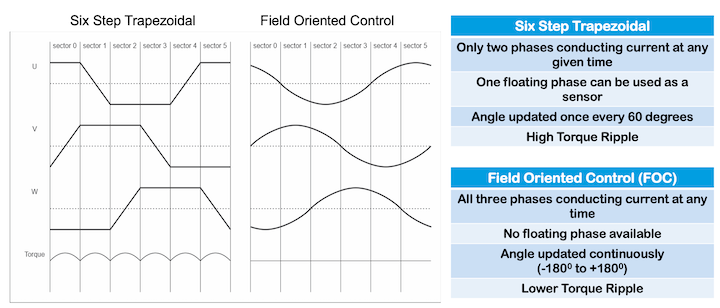
图1:梯形控制和FOC的区别
在采用梯形控制的设计中,电流仅在两个相位中传导;在浮动相位时,可以获取转子位置。此时,可监测反向电动势(BEMF)的值以推断转子位置。虽然BLDC电机设计通常具有较高的转矩纹波,但这种方法更简单,实施成本也更低。
PMSM电机的FOC实现在三个相位中的每一个相位均导通电流;每个相位的电流、电压,与其它相位的电流、电压偏移120度。这种方式最大限度地减少了转矩纹波;电机角度也连续更新。此类正弦波控制主要用于PMSM电机,需要更复杂的电子监测控制电路。使用FOC控制直流电机基本上等同于交流电机的控制。
如图2所示,转矩由电流控制环路监测和控制。来自三相逆变器的反馈信息被馈送至电流感应电路,并中继到控制回路,以保持精确的扭矩水平。电机位置模块对电压和电流值进行采样,通过一系列变换操作获取电机的角度和速度。/p>
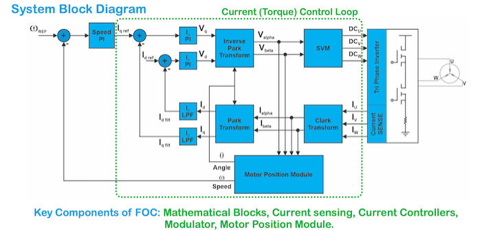
图2:基于FOC实现的基本组件
其他要点
前文对FOC基本原理的概述,为您展现了一个坚实的框架模型,以便更好地理解固件如何用于个别功能的配置。相关设计峰会视频对典型流程进行了更详细的解释,涵盖以下内容:
- Qorvo的FOC解决方案与可用IP列表,以及对部分功能的深入介绍
- 如何运行电机的分步说明,包括:
- 硬件设置
- 固件准备
- 电机参数识别——自动整定
- 通过GUI或调试好的电机参数文件(.xml)操作电机
- 调试工具及更多信息
电机控制技术的巨大进步,为充分利用BLDC/PMSM电机的效率、功率处理和可管理性并进行创新产品设计提供了大量机会。了解更多信息,请观看视频回放Qorvo 在线设计峰会: 面向三相 BLDC/PMSM 电机应用的现场导向控制。